I saw on a forum someone who was having problems with their mesh bed level. The advice that they were given was to disable the feature and use the screws tilt adjust features in the firmware. Here is what each of those features do.

Screws tilt adjust, in most firmware packages, allows you to set the distance between the bed and the nozzle. It does this in each of the four corners of the bed and in the center of the bed. The benefit of doing it this way is that it’s pretty simple to get started and the results are typically decent. No need to fix it if it ain’t broke. The downside of this method is that it assumes a pretty flat bed in between those points. If it isn’t, the firmware won’t be able to account for the variations simply because they haven’t been compensated. This was my situation. After replacing a warped bed a number of times I decided that it was time to do something different.

Mesh bed level. This method is more work to get set up, but it does account for a warped bed. To set up a mesh bed level, the firmware will allow the user to select a grid, usually 3×3 or 5×5. This grid is used to compensate for any warpage that may be present in the bed.

My typical approach is to mechanically make the bed as flat as possible. By adjusting the clamping pressure on each corner of the bed you can manipulate it to flex more. For now, don’t worry about the orientation, we’ll deal with that later. Once you get a bed that’s pretty flat, let’s go ahead and adjust the bed screws manually. Run the function to adjust the bed screws and make sure that your orientation is as good as you can make it. Next, adjust your mesh bed level. Some people do this before each print, I don’t. My environment is pretty stable so I just leave mine set up and run a mesh bed level from time to time.

I read a user’s help request in an online forum that was interesting because it illustrates what can happen from time to time. The symptom that the user was experiencing was that there was way too much squish in their first layer of printing. It was almost non-existant.

They were stumped for a while as to what the cause was. In reading through their comments and the things that they tried, it turned out that they had a BLTouch. Basically, what had happened was that they had set up a mesh bed level manually, and then they allowed the BLTouch to override that stored level. A misconfigured BLTouch was the culprit, in this case. It was going through the motions, but it was storing an inadequate bed level, which was overriding the valid mesh bed level that they had stored previously.

Someone recently showed a picture of their 3d printed 25mm calibration cube. Unfortunately for them, however, it was not a cube at all. It was a 25mm x 12.5mm x 20mm shape. 

When digging into the problem a little bit, it turns out that they had changed some stepper motors and firmware and accepted all of the default values. If the firmware has not been specifically written for your printer, the default values are most likely wrong. Same thing for the stepper motors. If you replace stepper motors, make sure that your X, Y, and Z steps are correct. Using Marlin based firmware, you can set your X, Y, Z and E steps in the firmware before flashing or you can use the M92 command to update. Using Klipper firmware, you must set your rotation distance.

Right out of the box, Cura is pretty powerful. But, sometimes you still just need a little extra functionality. Fortunately, Cura makes this pretty easy to implement. Here is how I do it. Once I figure out which plugin I want to use, I add my login information into Cura. This synchronizes the software on my laptop to my account on the cloud. Then I go to the Ultimaker Marketplace on the web and find the plugin directory. You can add plugins from Cura itself, but I have found it to be very laggy and difficult to use so I just do it from the web. Pick the plugin(s) that you want and add them to your account. Restart Cura and it will ask you to synchronize your account.  

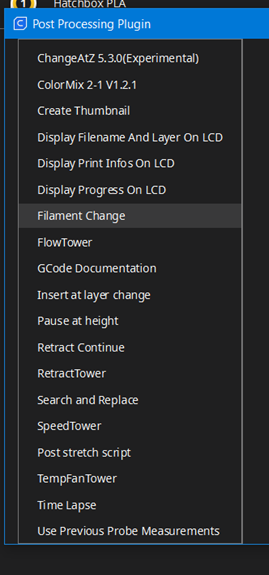
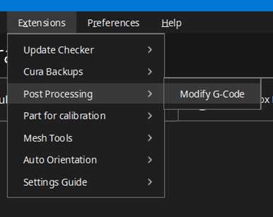
Sometimes, you run out of filament in the middle of your print and need to change it. Other times, you intentionally want to change your filament. For example, you might want to start a print with gold and finish with black. This post is about how I do that. If you already have the plugin setup, go to Extensions, Post Processing, Modify G-Code. Press “Add Script” (the only option available) then select Filament Change. You will need to figure out what height you want the change to occur at, and then convert that into layers. At a 0.2mm layer height, 10mm would be layer 20, for example. From there, just slice your model as normal and Cura will include the command to change filament.

Changing your printer Nozzle

Sometimes you need to change your nozzle. I do this most frequently when I change filament materials or when I need more details. I made a jewelry box for my wife last year and I used a wood PLA filament. Most hobby printers (including mine) use a default 0.4mm nozzle tip. The wood clogged my tip, so I switched it out to a larger tip. Other times, I want to print figurines for my kids with a lot of details so I want to switch to a smaller tip.

Here is what I do:

  • Heat up the extruder. I’ve found that the hot end material contracts around the nozzle tip. Heating it up expands the hot end and makes the nozzle easier to remove.
  • Remove the old tip
  • Insert the new tip
  • Adjust the nozzle size and line width in Cura (or other preferred slicer)
  • Calibrate e-steps to compensate for new flow rate
  • PID tune to adjust heating properties
  • Level bed